TEST PROCEDURES
A2.1
GENERAL CONDITIONS FOR TESTING
(1) Unless otherwise stated in this Specification, the tests are to be carried out under the normal operating conditions of connection to the Telecom network, and with the equipment operating as intended.
(2) All claimed product functions requiring compliance with this Specification shall be tested.
(3) Not all requirements of this Specification are included in the Test Schedule in Appendix No. 3. The schedule includes only those requirements which are considered consistent with acceptable performance. However, Access Standards reserves the right to amend the Test Schedule should ongoing experience reveal that this is necessary.
(4) The primary aim of the test programme is for the independent Testing Authority to be able to satisfy itself that the product under test does in fact comply with Telecom requirements (and therefore is not likely to cause trouble to either the user or the Telecom network, or to lower customer perception of network performance).
(5) The performance criteria quoted in this Specification are regarded as true values. Testing Authorities will be required to indicate the measurement uncertainty in cases where the test result fails that specified by a small margin. The uncertainty may be used to adjust the calculated mean of any marginally failing test result in the Applicant's favour. In general, component tolerances of test set-ups should be ±1%.
(6) Tests are made in any order except where otherwise specified. Where testing involves taking measurements at different currents or line lengths, measurements are made at the lowest current first, increasing sequentially to the highest, in order to avoid a heating effect on the line test circuit.
(7) The tests are made with the appropriate cordage and plug attached and with the device connected to the relevant test circuit via the new Telecom standard 2-wire line termination and jackpoint combination (see Technical Document TNA 102 Fig. 6 (c) for component and wiring details). The 2-wire jackpoint shall satisfy the requirements of Specification PTC 223.
(8) For apparatus which must be used with protection barriers or line isolating units, the specified type is connected in its normal position for the tests.
(9) Where the device is reliant on more complex equipment for its operation, arrangements may be made for assistance to be given, by the Applicant, to the Testing Authority for the test set-up. Such arrangements will be at the discretion of the Testing Authority.
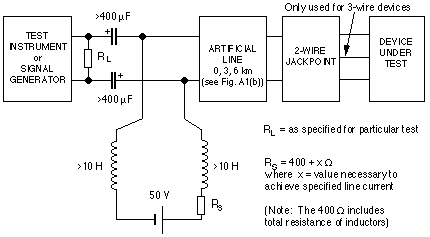
(10) Where called for, performance shall be assessed against an artificial line made up of sections of maximum length 0.5 km (ref. Fig.A1(b)), providing an adjustable line length of from 0 to 6 km. (For preference, line lengths of 0.1 km should be used, each consisting of two series resistors of 8.4 ohm and two parallel capacitors of 2.5 nF as shown in Fig. 4-1(b).)
(11) Test procedures for several parameters are specified for different values of line current. The source resistance (Rs) is adjusted to obtain the current required for each test (see Fig. A1). Alternatively, these tests may be performed by switching discrete values of Rs as follows:-
| APPROXIMATE LINE CURRENT | Rs |
APPROX. EQUIVALENT LENGTH of 0.5 mm ARTIFICIAL LINE |
| Full current | 400 ohm | 0 km |
| 45 mA | 400 +350 ohm | 2 km |
| 30 mA | 400 + 850 ohm | 5 km |
| 25 mA | 400 + 1350 ohm | 8 km |
| 20 mA | 400 + 1750 ohm | 10 km |
* The above are approximately equivalent only.
* There is no requirement to test above 80 mA. If full current is greater than 80 mA, it may be adjusted down to that value by increasing the value of Rs.
(12) Simple functional tests may be carried out to ensure that the equipment is operational to the extent that calls may be initiated, answered and terminated reliably under a typical range of line conditions, and to confirm that the basic functions of the equipment can be demonstrated.

FIG. A1(a) TEST SET-UP

FIG. A1(b) ARTIFICIAL LINE SEGMENT (0.5 km Line Length)
A2.2
TEST SET-UP PROCEDURES
A2.2.1
This Specification covers a wide range of equipment types and actual tests required will vary from item to item. The Testing Authority will have to use some discretion in defining the test programme necessary for each case. This will depend on the functions offered by the product under test.
A2.2.2
Clause-by-clause procedures
The following Clause numbering corresponds with that used in the body of this Specification and the Test Schedule in Appendix 3.
4.1
General (also ref. clause 4.14)
(1) (c) Where adjustable volume controls are fitted on telephony devices, two sets of tests will be required for the parameters affected. The tests are necessary to determine the effects of the volume control and ensure that there is at least one setting at which the transmission performance requirements are fully complied with.
The tests affected are to clauses 4.2 to 4.13 of this Specification and each should be carried out with the volume control set in turn to both "minimum" and "maximum".
(2) In most cases where a proprietary interface is involved, it will only be necessary to test the combination of non-terminating series-connected device and terminal device. However, if the interface can function as proprietary or standard depending on the number of individual connections used, then the series-connected device should also be tested as such on its own.
* Typical examples are some small PABX/KTS's with extension interfaces which are basically designed for proprietary telephones and consist of, typically, separate 'data' (or signalling) and 'voice' connections. In some such cases, standard 2-wire telephones can be connected using the 'voice' connections only.
4.2
Transmitted power limitations
The test set-up for checking the transmitted power levels is shown in Fig. A1, using zero length line and a 600 ohm non-reactive resistor as RL. Tests shall be carried out at current values of 40 mA and full current (or 80 mA).
(1) (a) & (b) Signals should be measured over their full period, or over 1 minute for longer duration signals. It is acceptable to measure a large number of instantaneous values over this period, and then average these values.
(c) The maximum value of instantaneous power is to be measured by recording the highest peak measured during a 1 minute period of normal transmission. The tests should be made for all combinations of speed and modulation in multiple speed equipment.
(2) For the acoustic stimulus test of telephony devices, the measuring instrument must be calibrated in dBV rms. Sinusoidal signals are applied to the mouth reference point at a sound pressure level of 20 dBPa at a frequency of 1 kHz.
(3) & (4) The transmitted power level of recorded speech shall be measured using a VU meter and associated adjustable attenuator as follows:-
(a) The adjustable attenuator, which should have a control graduated in VU's, is to be connected such that the signal being measured is applied to the VU meter via the attenuator.
* A correctly calibrated VU meter with active input will give a reference deflection (0 VU) when bridging a transmission line at a point where a sinusoidal voltage exists which develops 1 mW in a resistance of 600 ohm (0 dBm).
* Since the impedance of the DUT should be 'BT 3' rather than 600 ohm, an error is introduced when measuring. However, this error is ignored for the purpose of these measurements.
(b) When monitoring telephone speech signals, the measurement is determined by the greatest deflections on the meter occurring in a period of about 5 to 10 seconds. One or two occasional deflections of unusual amplitude should be ignored.
(c) The attenuator should be adjusted until the deflections, interpreted as described in (2) above, just reach the scale point corresponding to reference deflection (0 VU). The volume in VU is determined by the markings on the attenuator control at the setting thus obtained.
(d) If for any reason the deflections cannot be adjusted to the reference deflection, the measurement is given by the algebraic addition of the attenuator setting and the actual deflection as read on the meter scale.
* Equivalent test results using one of the internationally recognised peak programme meters (ppm) will also be accepted. In such cases the ppm standard used should be stated with the results so that they can be correctly evaluated.
(e) The speech recorded for test purposes should be from a standard source established by the Testing Authority for this purpose.
(f) The same recording shall be used for testing power levels and for the subjective assessment of speech quality (ref. clause 4.16).
* VU meters For further information on VU meters, reference should be made to the CCITT White Book referred to above. However, copies of that document may be difficult to obtain in New Zealand and for this reason the following information is given:-
Characteristics of VU Meter
(1) If a sinusoidal signal in the frequency range 35 Hz to 10,000 Hz, of an amplitude which causes a reference deflection of 0 VU under steady-state conditions, is applied to the meter then that meter shall initially register 99% of the reference deflection within 0.3 seconds (± 10%). It shall then overswing the reference deflection by 1- 1.5%.
(2) The total time required for the meter pointer to reach its position of rest on the removal of the signal shall not be greatly different from the time of response.
(3) The variation of response with frequency from that at 1 kHz shall be within the following limits:-
(a) No more than 0.2 dB between 35 and 10,000 Hz.
(b) No more than 0.5 dB between 25 and 16,000 Hz.
(4) The point of reference deflection shall be marked '0 VU'. The remainder of the scale shall be graduated in VU above and below reference deflection.
4.3
Noise and crosstalk
The test set-up for testing noise and crosstalk levels is shown in Fig. A1, using zero length line and a 600 ohm non-reactive resistor as RL. A measuring instrument of high input impedance is connected across the 600 ohm resistor, calibrated in units of dBmp (using psophometric weighting in accordance with CCITT Blue Book, Rec. O.41). Tests shall be carried out at full current (or 80 mA).
4.3.1
Equipment on-hook
(1) The noise level is measured by averaging over a minimum period of 1 second. The measurement is made three times and the highest value of the three measurements is selected as a determination of the noise level.
(2) For noise signals above 4 kHz, a spectrum analyser with the capability of measuring frequencies up to at least 150 kHz shall be used, connected as above. The analyser shall be set up to average no less than 50 samples.
4.3.2
Equipment off-hook
For all noise tests with the equipment off-hook, the test set-up is as above but with the microphone of any telephony device replaced by a resistor of value equivalent to the resistance of the microphone at 1000 Hz.
(1) (a) Noise signals in the 300 Hz - 4000 Hz range shall be measured as in clause 4.3.1 (1) above.
(b) Signal to noise ratio should be tested at 1000 Hz. Where the record level is adjustable, the input test signal will be adjusted so that the associated VU meter indicates 0 dB. * It is assumed that any equipment having automatically controlled recording levels will be already set to this level.
(d) Noise signals above 4 kHz shall be measured as in clause 4.3.1 (2) above.
(2) Signal to noise ratio should be tested using a signal of 1000 Hz set at a level equivalent to the lowest transmit level of any signal frequency in the range 300 Hz to 3400 Hz used by the device. The noise signals both above and below 4 kHz shall be measured as in clause 4.3.1 above.
4.3.3
Multi-line devices
A 1000 Hz test signal shall be applied to one line at a level of 0 dBm and crosstalk
isolation measured on each other line on the device. For the off-hook condition, the microphone of each handset on the device shall be replaced by a resistor of value equivalent to the resistance of the microphone at 1000 Hz.
4.4
Distortion
(1) (b) Total send harmonic distortion of devices transmitting recorded speech or music should be measured using a signal frequency of 1000 Hz. Where the record level is adjustable, the input test signal shall be adjusted so that the associated VU meter indicates 0 dB.
* It is assumed that any equipment having automatically controlled recording levels will be already set to this level.
(c) Total send harmonic distortion introduced by non-terminating devices should be measured using a signal frequency of 1000 Hz applied at a level of -4 dBm.
4.5.1
Off-hook impedance
(2) & (3)
(a) The minimum Return Loss and Echo Return Loss of the device against a reference impedance of BT3 shall be measured at the line terminals, with the telephone off-hook and supplied from a high impedance d.c. feed (see Fig. A1). The microphone on each telephony device tested shall be replaced by a resistor of value equivalent to the resistance of the microphone at 1000 Hz.
Measurements shall be made at both 20 mA and full current (or 80 mA) on a
0 km line.
(b) The test signals shall be of the standard frequencies 300 to 3400 Hz in
100 Hz increments, preferably at a level of -10 dBV. Tests made with closer frequency separation are acceptable provided that the full range is covered.
* The test signal level of -10 dBV may not always be achievable on all test instruments, and is therefore only stated as a preference to Test Laboratories.
(6) For devices equipped with a "hold" facility, echo return loss will be measured as above but with the device on-hook and the "hold" condition activated.
4.5.2
On-hook impedance
The on-hook impedance shall be measured at the line terminals, with the device in the on-hook condition and connected to a high impedance 50 V d.c. feed (ref. Fig. A1) via a 0 km line.
Measurements shall be made by applying 1 Vrms over the frequency range 300 Hz to 3400 Hz at 200 Hz intervals, using a known source impedance. The required impedance magnitude at each frequency is calculated from the voltages across the known source impedance and impedance of the device.
4.6.1
Terminating devices
(1) & (2) The line port impedance of terminating series connected devices shall be tested as in clause 4.5.1 above, with the terminal equipment port terminated with a reference BT3 network.
4.6.2
Non-terminating devices
As for terminating devices.
4.7
Impedance of bridging equipment
The impedance of bridging equipment shall be measured as in clause 4.5.2 above.
4.8
Impedance balance ratio to earth
Impedance balance ratio to earth shall be measured with the equipment in both on-hook and off-hook conditions, using the test set-up shown in Fig. A2. The test shall be performed with V1 set at 1 Vrms and Rs set at 400 ohm.
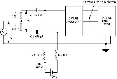
FIG. A2 MEASUREMENT OF IMPEDANCE BALANCE RATIO TO EARTH
4.9 & 4.10
Frequency response and Loudness Ratings
NOTE: Some of the following clauses relate to electro-acoustic tests of telephony devices. The basic requirements for such tests are as follows:-
(a) All electro-acoustic tests are to be carried out in an environment where the ambient noise is insufficient to influence the acoustic measurements being made.
(b) The setting up of the mouthpiece and earpiece shall be as follows:-
(i) Where the mouthpiece of the handset is fixed relative to the earpiece, the handset is placed in the loudness rating guard-ring position as described in CCITT Blue Book, Recommendation P. 76, Annex A.
(ii) Where the mouthpiece of the device is not fixed relative to the earpiece, the front plane of the mouthpiece is mounted 15 mm in front of the lip ring and coaxial with the artifical mouth.
(iii) The earpiece is sealed to the knife-edge of the artificial ear.
4.9.1 Send frequency response of telephony devices The telephony device is connected to the test equipment as shown in Fig. A1 with RL set at a value of 600 ohm resistive, a line length of 0 km, and current set at 20 mA. Measurements shall be made:-
(a) using the 14 test frequencies specified in Table 1, or
(b) making a continuous sweep across full frequency band specified.
The send sensitivity Smjn is determined by the procedure described in ITU-T Recommendation P.64:1993. The output voltage is measured at the fundamental frequency of the stimulus. The results are expressed in dBV/Pa.
4.9.2
Receive frequency response of telephony devices
The test set-up is the same as for send frequency response (ref. clause 4.9.1 above)
with the generator set to deliver an e.m.f. of -10 dBV.
The receive sensitivity, Sjen is measured as a function of frequency as described in ITU-T Recommendation P. 64:1993. The sound pressure is measured at the fundamental frequency of the stimulus. The results are expressed in dBPa/V.
4.9.3
(Frequency response of) non-voice equipment
(3) On devices that transmit frequencies above 3400 Hz, check that operation between units continues when the frequency range is restricted to 300 - 3400 Hz.
For this test, a suitable low pass filter with a cut-off frequency between 3400 Hz and 3500 Hz shall be inserted in the connection between units.
4.9.4
(Frequency response of) series connected and bridging devices
(1) (a), (b) & (c) On non-terminating series connected and bridging devices, the insertion loss is to be measured between the line port and terminal equipment port using 600 ohm terminations on both the frequency generator and level measuring instrument. Measurements shall be taken at 300 Hz, 500 Hz, 1000 Hz, 2000 Hz, 3000 Hz and 3400 Hz.
(d) Series connected devices in the terminating state shall be measured as above in the off-hook condition.
(2) For proprietary interface devices, the combination of terminal and series connected device shall be tested as in 4.9.1 and 4.9.2, or 4.9.3, as appropriate.
4.10
Send and Receive Loudness Ratings (telephony devices)
(1), (2) & (4) The telephony device is connected to the test equipment as shown in Fig. A1 with RL set at a value of 600 ohm resistive, a line length of 0 km.
The tests are performed with line currents of 20 mA, 45 mA and full current (or 80 mA) at the 14 frequencies, fn, shown in Table 1, to obtain values for the send sensitivity, Smjn, and receive sensitivity,Sjen, of the line test circuit.
The send loudness rating, SLR (in dB), is calculated from the following formula:-
| 14 | ||
| SLR = -10/0.175 log10 | Σ | 100.0175(Smjn - Wsn) |
| n=1 |
where:-
Wsn is the send weighting factor given in Table 1.
Smjn is the send sensitivity of the line test circuit (in dBV/Pa).
The receive loudness rating, RLR (in dB), is calculated from the following formula:-
| 14 | ||
| RLR = -10/0.175 log10 | Σ | 100.0175(Sjen - LEn - Wrn) |
| n=1 |
where:-
WRn is the receive weighting factor, given in Table 1;
LEn is the real ear loss, given in Table 1 (in dB).
Sjen is the receive sensitivity of the line test circuit (in dBPa/V).
(6)&(7) The above SLR and RLR tests are then to be repeated using the artificial line lengths of 0km, 3 km and 6 km.
| n | fn (Hz) | LEn (dB) | WRn (dB) | WSn (dB) | WMn (dB) |
| 1 | 200 | 8.4 | 85.0 | 76.9 | 86.4 |
| 2 | 250 | 4.9 | 74.7 | 62.6 | 81.9 |
| 3 | 315 | 1.0 | 79.0 | 62.0 | 78.5 |
| 4 | 400 | -0.7 | 63.7 | 44.7 | 78.2 |
| 5 | 500 | -2.2 | 73.5 | 53.1 | 72.8 |
| 6 | 630 | -2.6 | 69.1 | 48.5 | 67.6 |
| 7 | 800 | -3.2 | 68.0 | 47.6 | 58.4 |
| 8 | 1000 | -2.3 | 68.7 | 50.1 | 49.7 |
| 9 | 1250 | -1.2 | 75.1 | 59.1 | 48.0 |
| 10 | 1600 | -0.1 | 70.4 | 56.7 | 48.7 |
| 11 | 2000 | 3.6 | 81.4 | 72.2 | 50.7 |
| 12 | 2500 | 7.4 | 76.5 | 72.6 | 49.8 |
| 13 | 3150 | 6.7 | 93.3 | 89.2 | 48.4 |
| 14 | 4000 | 8.8 | 113.8 | 117.0 | 49.2 |
NOTE: Values for fn are taken from BS 3593:1963.
TABLE 1: PARAMETERS REQUIRED TO CALCULATE SLR, STMR AND RLR
4.11.3
Sidetone Masking Rating (STMR)
The telephony device is connected to the test equipment as shown in Fig. A1 with RL set at a value of 600 ohm resistive, a line length of 0 km. The test is performed with line currents of 20 mA, 45 mA and full current (or 80 mA). The test is then repeated with RL set at BT3. For each of the 14 frequencies, fn, the sidetone loss of the line test circuit is determined by a procedure consistent with that described in ITU-T Rec.
P. 64:1993.
(a) The sidetone loss, LMeSTn, is calculated from the formula:- LMeSTn = 20 log10 (Pmn/Pen)
where:-
Pmn is the free field sound pressure at the mouth reference point (in Pa);
Pen is the sound pressure generated in the artificial ear (in Pa).
(b) The masked sidetone loudness rating, STMR (in dB), is calculated from the formula:-
| 14 | ||
| STMR = -10/0.225 log10 | Σ | 10-0.0225(LMeSTn + LEn + WMn) |
| n=1 |
where:-
WMn is the sidetone weighting factor, given in Table 1; LMeSTn is the sidetone loss (in dB);
LEn is the real ear loss, given in Table 1 (in dB).
4.12
Instability test
(1) Check stability of normal operations of all devices, other than telephony devices, when connected as in Fig. A1 with a 0 km artificial line and a BT3 network connected in place of RL. This check shall be carried out with line currents of 20 mA and full current (or 80 mA).
(2)&(3) For telephony devices the test set-up is as shown in Fig. A1 with 0 km artificial line. The handset is placed (off-hook) face down on a hard flat surface for the duration of the test. With the line current set at 20 mA, checks are to be made for any sustained audible oscillation emitted by the device when each of the following alternative terminations are used in place of RL:-
(a) A 270 ohm resistor, and,
(b) a 1600 ohm resistor in series with a 510 nF capacitor.
This test is to be repeated at full current (or 80 mA). Also, for devices fitted with a user-controlled receive volume control, the checks are to be made with the volume control set at both maximum and minimum positions.
4.13
Acoustic shock tests (of telephony devices)
The telephony device is connected to the test equipment as shown in Fig. A1 with RL set at a value of 600 ohm resistive, a line length of 0 km and full current (or 80 mA).
The generator is set to deliver sinusoidal signals at an e.m.f. of +24 dBV r.m.s. at a frequency of 1kHz.
4.14
Adjustable volume control
See clause 4.1.
4.15
Telephony security in on-hook condition
The telephony device is connected to a line in parallel with another telephony device. With the first device on-hook, a call is established from the second device and conversation should proceed. The first device, while still on-hook, should then be monitored subjectively to ensure that no evidence of speech can be detected within 300 mm of the device.
4.16
Recorded speech quality
The speech recorded for test purposes should be from a standard source established by the Testing Authority for this purpose. The recording shall be the same as that used for testing power levels (ref. clause 4.2). A subjective assessment of speech quality shall be made.
5.1
Signalling types
(4) While testing transmission security (ref. clause 4.15 above), a check shall be made to ensure DTMF signals cannot be transmitted while the device is on-hook.
5.2
Transmission of DTMF signalling
DTMF signalling shall be tested using the set-up shown in Fig. A1, with RL set at a value of 600 ohm resistive and full current (or 80 mA). For line powered devices, additional tests shall be performed at 20 mA line current.
5.4.4
Pulse rate and timing (decadic signalling)
Since decadic signalling is being discouraged for new products, full details of the test set-up requirements have not been included here. Testing Authorities have previously followed the procedures detailed in Specifications PTC 202, 211, 212, etc. and, where decadic testing is required, this should continue unchanged. Telecom is, however, no longer able to assist in the establishment of new decadic testing facilities.
5.6.1
Automatic dialling devices (general requirements)
Functional check and timing only required.
5.6.2
Caller display equipment
Functional check only required.
6.2
Function of d.c. line feed (polarity reversals)
(3) It will not be necessary to repeat all tests with the line polarity reversed. Having confirmed compliance with other performance requirements using a particular line polarity, a simple functional test with the polarity reversed shall be carried out to ensure that transmission and signalling are operational.
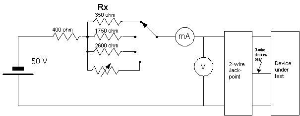
FIG. A3 TEST SET-UP FOR D.C. CHARACTERISTICS
6.3
Off-hook d.c. line Characteristics
The DC characteristics shall be tested using the set-up shown in Fig. A3. The voltage and current measurements shall be taken with the resistance 'Rx' set to 2600 ohm, 1750 ohm and 350 ohm respectively (approx. 15 mA, 20 mA and 45 mA).
6.5
Hold condition (if provided)
(2) With the 'hold' facility activated, the off-hook line current shall be adjusted to
20 mA by varying 'Rx' with the device connected to a 400 ohm, 24 V dc source (ref. Fig. A3). The line current shall be checked when an additional 40 ohm resistor is placed in series with the source and the source voltage is reduced to 21 V.
* The above tests confirm correct operation of the device under worst limit conditions when connected to a nominal 24 V, 400 ohm source, i.e. 24±3 V and 400±40 ohm.
(3) & (5) The test set-up in Fig. A3 shall be suitably modified for these tests and the timing requirements checked.
6.7
On-hook line current
With the device connected to the 50 V battery via a 1500 ohm resistor, the current drawn shall be checked under both normal and reversed line conditions. The value to be recorded shall be the higher of the two measurements taken.
6.8
Recall and call waiting
For equipment with "TBR" ("recall") and/or "call waiting" key function, the device should be connected as shown in Fig. A3 in the off-hook state, with 'Rx' set at 1750 ohm (or current set at 20 mA). The duration of the timed break shall then be checked when the 'recall' key is operated.
6.9.1
D.C. line characteristics (series connected equipment)
(1) The test set-up is as shown in Fig. A4, but with a reference telephone connected to the terminal equipment port. With the telephone off-hook, the volt drop is measured between ports with feed currents of 20 mA, 30 mA, 40 mA and full current (or 80 mA).
(2) On devices which perform a switching function during ringing, the 'in-rush' current is checked as the switching takes place.
(4) Clauses 6.3 to 6.8 shall be checked using the test set-up with reference telephone used in (1) above.
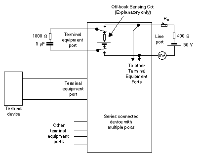
FIG. A4 TEST SET-UP FOR SERIES CONNECTED DEVICE
6.9.4
Line grabbing equipment
(1) A suitable test set-up, using a reference telephone connected to the terminal equipment port, shall be used to enable the timing requirements to be checked.
6.10
D.C. line feed to other devices
(4), (5) & (6) Test measurements to be carried out using a reference telephone connected to the port under test.
6.11
Fail-safe requirements
Functional checks only required.
7.1
General
(7) The test method (see 7.5 & 7.6 below) for Ringing Number quantifies both sensitivity and loading on a scale of 0.5 - 5. The test set-up is shown in Figure A5. Because of the adoption of 2-wiring, 3-wire CPE will be rated connected via a 2-wire socket. The sensitivity test also covers sensitivity to cadence timing.
The RN shall be measured and recorded for each of the Distinctive Alert ringing cadences, and also separately for the on and off states of equipment with a ringer on/off option.
7.4
Audible characteristics of ringer
Minimum ringing acoustic output for "acceptance" is set very low at only 50 dBA. This may be assessed subjectively and it need only be measured where there is doubt whether this level is met.
7.5.1
General operation
Reliable operation is described as follows:-
(a) Devices with audible ringers
The ringer under test is required to follow the ringing cadence reliably by ringing audibly and "cleanly" with no hesitation or "stuttering". Electronic ringers often take longer to start with decreasing voltage, and this has the effect of shortening the ringing bursts within the cadence. Where there is a discernible shortening (by more than 5%) of the ring burst when one extra load is load is switched in, then the sensitivity shall be calculated with that load switched out.
(b) Auto Answer ringers
Reliable operation for an automatic answer device is determined by the equipment answering on application of ringing in the expected number of cadences. The test shall be repeated five times with the ring bursts lengthened
and shortened by 40 ms (see figure A5), and the equipment shall answer each time.

FIG. A5 CADENCE TOLERANCE
7.5.2
Ringer sensitivity
(1) (a) The test set-up for ringer sensitivity is shown in Fig. A6. The set-up shall be calibrated as follows:-
(i) Close switches Sw1 to Sw10.
(ii) Adjust the variable resistor until V1 = 107 Vp-p.
* It is important that this V is a true peak to peak measurement and not calculated from an r.m.s. measurement, as most ringers only conduct over part of the waveform.
(b) Sensitivity test procedure
Connect the device and close all switches. The ringing source is switched on and off in accordance with the cadence (DA1 - DA4) under test. If the ringer does not
operate reliably (see (2) below), the switches are opened one by one until the ringer does operate reliably. The Ringer Sensitivity number (RS) is derived as follows:-
RS = (10 minus the number of loads switched in) ÷ 2
All component tolerances to be ±1%
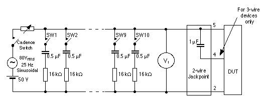
FIG. A6 RINGING TEST SET-UP
The above shall be repeated for each of the four Distinctive Alert cadences (DA1-DA4) and the following recorded:-
(a) Determine the codes to which the equipment does, or can be programmed to, respond to.
(b) Confirm that, when programmed for a specific code, the device does not respond to any other.
(c) Determine which codes the equipment responds to when:-
(i) it is not programmable, or,
(ii) is progammable, but not programmed for any specific code.
(d) Determine the functions which each code invokes.
(2) The ringer is tested for operation when the voltage across the ringer is reduced to 30 Vp-p. The test set-up is as per Fig. A6 with all 10 loads switched in and the variable resistor adjusted accordingly.
(3) To test response of the ringer to short ringing bursts, the test arrangement shown in Fig. A6 calibrated as in (1)(a) above should be used. Switches Sw1 to Sw10 should then be opened and the cadence switch operated to apply 40 ms bursts of ringing.
(4) To test impulse immunity, the equipment is connected to the test set-up shown in Fig. A7. Sw1 is switched on for 35 ms, off for 65 ms 10 times followed by a break of 750 ms. This sequence is repeated 10 times. Record whether or not the ringer operates when this sequence is applied.
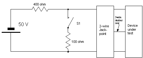
FIG. A7 IMPULSE IMMUNITY TEST SET-UP
7.5.3
Ringer Loading
Connect the Device under Test (DUT) as in Fig. A6, calibrate as per clause 7.5.2 (1)(a) and open switches Sw1 - Sw10.
(a) If the measured voltage falls below 107 V p-p when connected, the ringer loading and the resultant RN is to be assessed as greater than 5 and the ringer
is failed for excessive loading.
(b) If the measured voltage is above 107 Vp-p when connected, then switches
Sw1 - Sw10 are to be closed one by one until the it falls below 107 Vp-p. One switch is then opened again. The Ringer Loading number (RL) is defined as follows:-
RL = (10 minus the number of loads switched in ) ÷ 2
7.6
Ringing Number (RN)
The "Ringing Number (RN)" is defined as the higher of the Ringer Loading Number (RL), the Ringer Sensitivity Number (RS). If the resultant RN is zero, then it shall be rounded up to a value of 0.5.
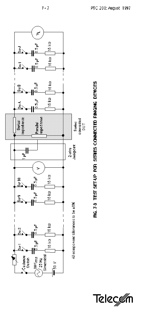
Fig. A8 TEST SET-UP FOR SERIES RINGING DEVICES
7.7
Series connected devices
7.7.1
General requirements
See clause 7.5.1
When measuring ringing parameters of a series device, the aim is to assign an RN to the device in such a way that the rules for adding RNs up to a maximum of 5 still apply. This means that the maximum applies to devices on both the load side and the network side of the device, plus the RN of the series device itself.
7.7.2
Devices without terminating facility
(1) (a) The test set-up for determining the RN is shown in Fig. A8. The set-up shall be calibrated as follows:-
(i) Close all switches Sw1 to Sw10, leaving switches SwA to SwJ open.
(ii) Adjust the variable resistor until V = 107 Vp-p.
* It is important that this V is a true peak to peak measurement and not calculated from an r.m.s. measurement, as most ringers only conduct over part of the waveform.
(b) Open all switches Sw1 to Sw10. Close switches SwA to SwJ one by one until the peak-to-peak voltage VL falls below 107 Vp-p, and then re-open one switch. The maximum load LRN (which represents the total RN that can be connected to the terminal equipment port of the device) is determined as follows:-
LRN = (number of switches closed ) ÷ 2 (Result must equal no less than 4)
(2) - (4) For devices which do not incorporate a ring detector, RNL is derived as follows:-
RNL = RL = 5 - LRN
Measure RN of the device with switches SwA to SwJ open as per clause 7.6. This value is defined as RNO.
The RN of the device is defined as the higher of the values RNL and RNO . Ringing Numbers of zero are rounded up to 0.5.
(5) If a device incorporates a ring detector, RN is derived as follows:-
(a) For devices which switch to the load on the terminal equipment port only after analysis of ringing has been completed - e.g. distinctive alert decoders,
RN shall be determined by assessing ringer sensitivity and loading as in 7.5 and 7.6 with the load disconnected (SwA to SwJ open).
(b) To determine the sensitivity of the ringer on devices which respond to ringing with the load connected to the terminal equipment port, check that it does operate with LRN loads connected (as determined in (1) above). If not, reduce LRN by opening switches SwA to SwJ one by one until the ringer operates according to the criteria of 7.5.1.
RNL is then derived as follows:-
LRN = (number of switches closed ) ÷ 2
RNL = RS = 5 - LRN
(c) Measure RN of the device with switches SwA to SwJ open as per clause 7.6. This value is defined as RNO.
The RN of the device is defined as the higher of the values RNL and RNO . Ringing Numbers of zero are rounded up to 0.5.
* The following information will be indicated on the PTC label:-
(a) Maximum aggregated RN which can be connected to the terminating equipment port of the series connected device (LRN ) as derived in 7.7.2(1)(b).
(b) RN for the series connected device as derived in 7.7.2(2).
7.7.3
Devices with terminating facility
For series connected devices with a terminating facility, test as in 7.5 and 7.6
7.7.4
Terminal equipment (or extension) ports
The requirements of this clause by observation and timing.
7.7.5
Locally generated ringing
(a) & (b) Ringing supplies to be tested against AS/NZS 3260.
(c) & (d) Ringing connection and cadence reproduction to be checked by observation and timing.
(e) & (f) Ringing waveform crest factor to be checked by examination using an oscilloscope.
(g) & (h) Use Test Set-up shown in Fig A8. Open all switches. Connect ringing source under test in place of the variable resistor, the cadance switch, the 80 V ringing source and the 50 V battery. Close switches SW1 to SW10 one at a time until the volatge falls below 107 Vpp. The number of switches closed is N. The RN that the ringing source can support is (N - 1)/2.
8
AUTOMATIC CALL SET-UP, ANSWERING & RECORDING FUNCTIONS
The methods of testing for this Section will vary from product to product and can best be determined by the Testing Authority in each case. Mandatory requirements specified can be checked by observation and manual timing of events.
9.1
Cordless devices (security)
(2) Establish number of security codes available and methods of allocation and regeneration. Confirm by functional test that device cannot be operated without security code.
10
NETWORK CONNECTION
The methods of testing for this Section will vary from product to product and can best be determined by the Testing Authority in each case. Mandatory requirements specified can be checked by observation and manual timing of events.
11
SUPPLEMENTARY SERVICES AND SPECIAL FEATURES
11.3
Distinctive Alert decoders
For the additional requirements not covered elsewhere in this Specification, the methods of testing can best be determined by the Testing Authority. Mandatory requirements specified here can be checked by observation and manual timing of events.
11.4
Analogue Calling Line Identification equipment
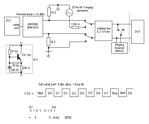
The test set-up for testing the additional requirements below (which are not covered elsewhere in this Specification) is shown in Fig. A9.
Notes:
Checksum = 2's complement of the modulo 256 sum of all words from the message type onwards
Modulo 256 sum = exclusive OR of each word
2's complement (X) = $00 - X
FIG. A9 TEST SET-UP FOR ANALOGUE CALLING LINE IDENTIFICATION EQUIPMENT
11.4.2
On-hook impedance
For this requirement, the method of testing can best be determined by the Testing Authority.
11.4.3
Ringing
The ringing detector (RN = 5) should respond to ringing with the DUT across the line.
11.4.4
Data capture
(1) The CLI device shall be checked to ensure it responds to both SDMF and MDMF on hook data generated by the Bell 202 modem.
* The data format is described in Technical document TNA 102, Section 10.
(2) Response shall be checked for all four DA ringing cadences. Timing requirements are given in Fig. A10.
(3) Response shall be checked with and without the ringing detector connected for each of the 0 km, 3 km and 6 km lengths of artificial line. Ringing detector shall remain operational when connected.
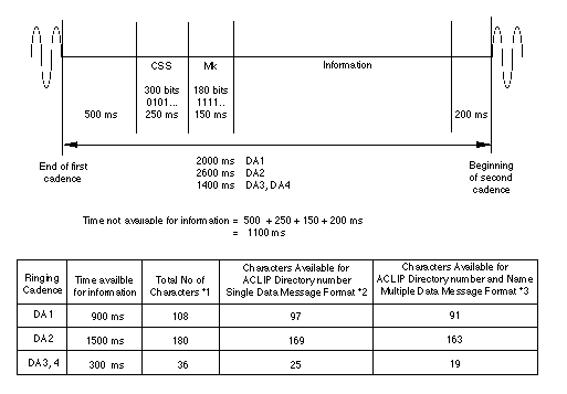
FIG. A10 TIMING DIAGRAM FOR ANALOGUE CLI SIGNALS
11.6
Data display
Establish whether call back number displayed is identical to number to be dialled. In particular, check insertion of prefix digit '0' for toll calls.