(1) The provision of any form of ringing detection is not mandatory for devices connected to the Telecom PSTN. If, however, a ringing detection device is connected across a line in the on-hook state, it shall comply with the requirements of this Section.
(2) There are four possible ringing cadences used which are known as 'Distinctive Alerts' (DA1-DA4). Full details of these are covered in Technical Document TNA 102. The requirements for identification of these cadences by decoding devices are included in this Section.
(3) Distinctive Alert decoders are divided into two categories as follows:-
(a) Type 1 - where the decoder is integral with the terminating CPE. In this case the CPE will only respond to a particular cadence (or cadences).
(b) Type 2 - where the decoder is in series with and separate from the terminating CPE, i.e is a 'series connected' device. Further requirements and design considerations specific to Type 2 decoders are covered in Section 11.
(4) It is possible for a decoder to fit both categories, e.g., a fax machine with an integral decoder for one cadence, and the capability of extending an additional cadence (or cadences) to separate devices such as an answering machine and/or a telephone. In such cases, the device shall be tested against the requirements for both Type 1 and Type 2.
(5) As an operational guide, the standard Telecom ringing supply is 25 Hz and the voltage at the customer's premises will generally lie in the range 30 - 85 V rms. Testing to this Specification is based on 38 V rms which is typical for a line with multiple CPE connected.
* See Technical Document TNA 102, Section 6, for further details on ringing supply.
(6) The shunt connection for ringer operation, which was mandatory in Specification PTC 202:1988, is now a non-preferred optional requirement for Telepermit (see also Section 10). The combination of a 2-wire jackpoint and a 3-wire device is treated as a 2-wire device for ringer test purposes. The preference, however, is for 2-wire connected equipment with DTMF signalling.
* Modification of 3-wire telephones to 2-wire is covered in clause 10.6.
(7) The requirements for ringer impedance and loading have been fully revised and the former "RAL" has now been replaced by a "Ringing Number (RN) ". The RN is derived from 'ringer sensitivity (RS)' and 'ringer loading (RL)'. The detailed method of assessment of these is covered below in clause 7.5 and clause7.6.
(8) Application of the "RAL" and "RN" are similar, and in many cases the numerical values will be the same. However, if ringing problems are encountered an any products having an earlier "RAL" number, it is recommended that such products be re-tested to this Specification for allocation of "RN", which is applicable to 2-wired installations. Return to Contents
7.2
Stand-alone ringers and alerting devices
(1) Stand-alone ringing devices have long been a common method of providing an auxiliary ringing facility. These include bellsets, sounders, lamp units, or other alerting devices which are not an integral part of another item of customer equipment.
(2) Older designs currently in use are suitable for connection to the previous standard 3-wire wiring arrangement, making use of the ringing (shunt) wire and not having an integral capacitor. As stated in clause 7.1(6) above the preference now for all CPE is for 2-wire connection with the capacitor incorporated, although this is only mandatory for CPE mounted outdoors (see clause 7.3 below).
(3) Ringers for interior use The requirements for stand-alone ringing devices designed for use within buildings on customers' premises are as follows:-
(a) New ringer designs intended for mounting within the customer's premises, and not exposed to the weather, shall be either:-
(I) plug-connected, using the standard BT plug to clause 10.2, or
(ii) provided with a suitable BT plug-ended connecting cord adapter to permit plug connection in those cases where the basic design was originally fitted with screw or IDC terminations.
(b) The plug ended cord supplied with a ringer should be no longer than 3 metres in length.
(c) The design of existing ringers, which have already been granted Telepermits, should preferably also be converted to plug connection at the earliest opportunity.
* Telecom's aim is for all customer equipment to be plug-connected so that customers have the opportunity to relocate their terminal equipment as and when necessary. This also provides the benefit that suspect equipment can be removed for fault investigation without the need for a service call.
* It is recommended that the suppliers of existing Telepermitted ringer designs provide suitable adapter cords, either as part of the product installation package or as optional extras. Also, it is recommended that any 3-wire connected product be converted to 2-wire connection by adding the integral capacitor.
(d) The line wires shall be terminated on pins 2 and 5 of the BT plug where an integral capacitor is fitted, or on pins 2 and 4 where the ringer is designed to use the shunt wire of a 3-wire installation or the capacitor of a 2-wire jackpoint.
* Note that there is an inherent reversal in the plug connections relative to the IDC connections of the 3-wire jackpoint. Pin 4 of the plug connects to the shunt wire, which is terminated on slot 3 of the jackpoint IDC connector. See also note under clause 10.2(2) and Technical Document TNA 102, clause 9.3(2).
(4) Ringers for exterior use See clause 7.3 below. Return to Contents
7.3
Externally mounted devices
All new equipment intended for mounting outside buildings or other weatherproof enclosures (i.e. all weather resistant devices) shall incorporate the following:-
(a) 2-wire connection with a capacitor of nominal value not greater than 1 µF in series with the detector (ref. Section 10)
(b) Screw or IDC terminals.
(c) Weather resistant cable access. Return to Contents
7.4
Audible characteristics
(1) The sound level for audible operation of a ringing detector, if provided, shall be at least 50 dBA when measured at 1 metre from the ringer in any direction while it is
mounted on a hard surface.
* It is recommended that a ringer be capable of producing a minimum acoustic level of 75 dBA. However, this is not mandatory.
(2) There are no further requirements (e.g. frequency) specified for the audible characteristics.
* The nature of the sound output signal and the frequency (or frequencies) used are regarded as marketing features. Return to Contents
7.5
Ringer sensitivity and loading
7.5.1
General operation
(1) During assessment of 'ringer sensitivity' and 'ringer loading', ringing detectors shall operate reliably, and any audible ringer shall be deemed to operate when it emits an audible signal compliant with clause 7.4.
* An audible ringing detector is regarded as operating 'reliably' when it rings audibly and 'cleanly' with no hesitation, 'stuttering' or shortening of the 'on' period.
* Note that 'operation' of a ringing detector does not mean answering a call. It simply means the reliable indication of the presence of ringing on the line.
(2) The sensitivity and loading requirements shall be tested for each of the four Distinctive Alert cadences (DA1-DA4), unless the device is set to differentiate between DA's and operate to only one of them. Where a device does not respond to all DA's, an indication of the DA's which the device does not respond to shall be included on the Telepermit label along with the 'RN' allocated (ref clause 7.6). Also, the following warning notice shall be included in the user instructions:-
"This device only responds to Distinctive Alert cadence(s) DA'x' "
(3) Where Distinctive Alert decoding is built-in (on equipment other than automatic answering devices), the ringing detector shall provide an alerting signal as soon as possible after completion of the decoding process and not more than 3 seconds after ringing is applied.
* The minimum time in which the decoding process can be completed is 1600 ms. Therefore, a distinctive alert decoder is required to extend ringing between 1600 ms and 3000 ms of ringing being applied.
(4) For a product to be claimed as compatible with a given Distictive Alert cadence, the ringing detector shall respond reliably to cadence "on" periods within the range of 360 ms to 440 ms. Also, although the following specified ringing cadence ranges for "on" periods are not mandatory requirements, performance shall be tested against them to provide an indication of their capabilities:-
(I) 320 ms to 480 ms.
(ii) 280 ms to 520 ms. Return to Contents
7.5.2
Ringer sensitivity
(1) Where ringing detectors are provided, the 'ringer sensitivity (RS)' on a scale of
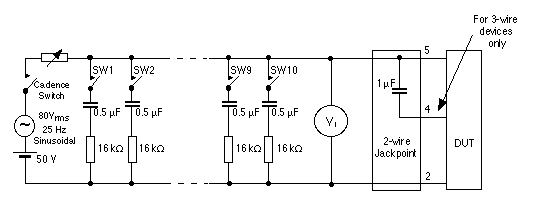
0 - 5 shall be determined using the test set-up shown in Fig. 7-1. The method used for determining 'RS' is described in detail in Appendix 2. This applies to both 2-wire and 3-wire devices.
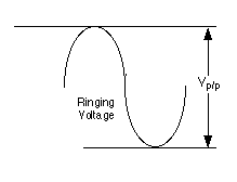
(2) Ringing detectors shall not operate to ringing voltages of 30 Vp-p or less.
FIG. 7-1 TEST SET-UP FOR 'RN' ASSESSMENT (3) Telephony devices shall be tested for ringing detector responce to applied ringing of 40 ms duration. If a ringing detector does respond, then the following warning notice shall be included in the user instructions:-
"This device may be subject to ringing or bell tinkle when certain other devices are connected to the same line. If this occurs, the problem should not be referred to the Telecom Faults Service"
* A typical example of this problem may arise if a customer uses the device in conjunction with a fax machine and Telecom's 'Faxability' service.
(4) Devices shall be tested for impulse immunity from any parallel connected device. If a ringing detector does respond to impulses, then the following warning notice shall be included in the user instructions:-
"This device may be subject to ringing or bell tinkle when calls are made from another device on the same line. If this occurs, the problem should not be referred to the Telecom Faults Service" Return to Contents
7.5.3
Ringer loading
As for ringer sensitivity, all ringing detectors shall be assigned a 'ringer loading (RL)' number on a scale of 0 - 5, which shall be determined using the test set-up shown in Fig. 7-1. The method used for determining this ringer loading number is described in detail in Appendix 2. This applies to both 2-wire and 3-wire devices.
Return to Contents
7.6
Ringing number (RN)
(1) The ringing number (RN) allocated shall be in the range 0.5 - 5 and shall be equal to the higher of the following:-
(a) Ringer sensitivity number (ref. clause 7.5.2).
(b) Ringer loading number (ref. clause 7.5.3).
(2) If the RN derived as above equates to zero, then it shall be rounded up to 0.5.
* Telecom reserves the right to increase the value of 'RN' above that derived in (1) and (2) if other factors, such as excessive 'on-hook d.c.', indicate the need. However, this is expected to occur in only rare and exceptional cases.
(3) For correct operation, the total of the RN's of all devices connected to a PSTN line at any given time should not exceed 5.
* Note that the RN assessment is not intended to be an accurate measurement, but is primarily a simple guide to customers as to the total number of items they may connect to a line.
(4) Where equipment is not intended to be connected to a line in parallel with other terminal equipment, this shall be clearly stated in the user instructions.
* Some items of series connected equipment do not normally have other devices connected in parallel with their PSTN line port. In cases where this possibility is envisaged, then the factors influencing the RN should be considered in the design. Return to Contents
7.7
Series connected devices
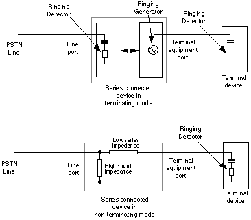
* See clause 2.12 and Fig.7-2 for explanation of series connected devices.
7.7.1
General requirements
The requirements for general operation stated in clause 7.5.1 shall be applied equally to series connected devices.
FIG. 7-2 TERMINATING & NON-TERMINATION SERIES CONNECTED DEVICES Return to Contents
7.7.2
Devices without a terminating facility
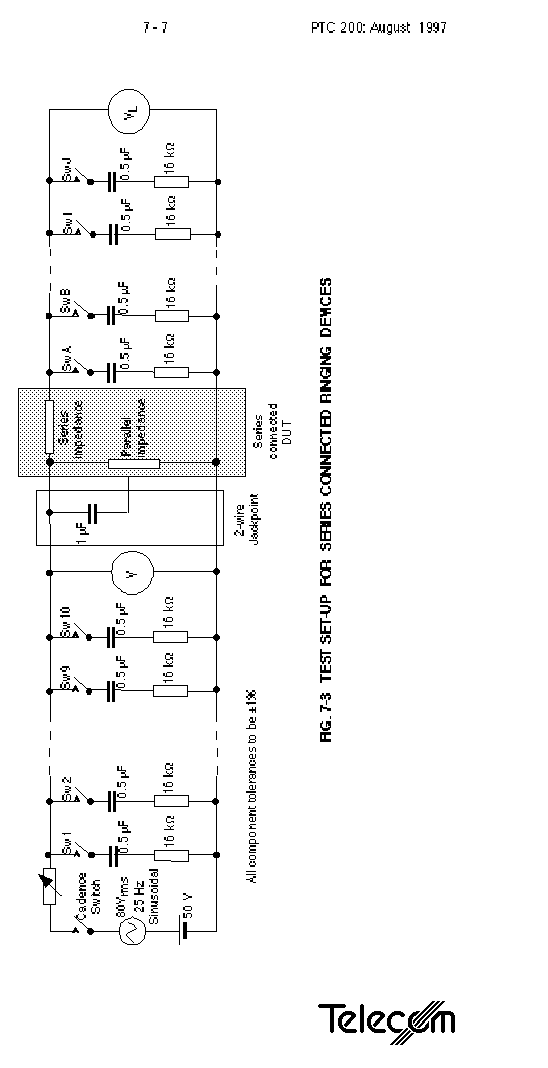
(1) Series connected devices which do not have a terminating facility shall be tested using the test set-up shown in Fig. 7-3. (Details of the test methods are given in Appendix 2.)
(2) All such series connected devices shall be allocated a ringing number RN, as described below.
(3) All such series connected devices shall extend ringing to their terminal equipment ports such that a "ringing load" (LRN) having a total RN of not less than '4' shall operate satisfactorily, when ringing is applied to the line port. The ringer loading number (RL) of the series connected device shall then be derived as follows:-
RL = 5 - LRN
* This means that the Ringer Loading of all such devices cannot exceed a value of 1.
FIG. 7-3 TEST SET-UP FOR SERIES CONNECTED RINGING DEVICES
(4) For devices which do not detect or respond to ringing, this Ringer Loading number shall become the RN of the device, because there is no ringer sensitivity.
(5) All such series connected devices which respond to ringing shall be tested for ringer sensitivity and the RN derived as follows:-
(a) For devices which disconnect the terminal ports while responding to the first cadence of incoming ringing from line, ringer sensitivity and RN shall be assessed in accordance with clause7.5.2 and clause7.6, with the terminal ports disconnected.
* A common example is a distinctive alert decoder which responds to the first cadence of incoming ringing, and then extends subsequent cadences to a terminating equipment port. Such a device has to be assessed for ringer sensitivity during the first cadence when the terminating ports are disconnected and there is no ringing load.
(b) For devices which respond to ringing, but have their terminal ports connected at the same time, sensitivity and RN shall be assessed by varying the ringing loads connected in parallel with the line and terminal equipment ports.
(Details of the test method are given in Appendix 2.)
* In some cases, the line ports of series connected devices are not expected to be connected in parallel with other devices. However, the possibility of this occurring has to be allowed for. Return to Contents
7.7.3
Devices with terminating facility
Series connected devices capable of a terminating function shall comply with the requirements of clause 7.5 and clause7.6.
Return to Contents
7.7.4
Terminal equipment (or extension) ports
(1) Series connected equipment shall not connect ringing to any terminal port which is in the off-hook condition. Similarly, after ringing has been applied to a port, it shall be disconnected within 100 ms of detection of an off-hook condition.
* This requirement applies to the application of either network ringing or locally generated ringing.
(2) Series connected equipment designed to extend calls to a terminal equipment port via a 4-wire path shall be capable of reproducing, at the terminal equipment port, the original ringing cadence received at the PSTN line port. The timing distortion of the cadence produced between the two 2-wire ports shall not be in excess of ± 5 %.
* If timing distortion is excessive, it is recommended that the correct cadence is regenerated.
(3) All terminal equipment ports on series connected equipment designed to accommodate any Telepermitted device shall support both 2-wire and 3-wire connection or carry a suitable warning if 3-wire connection not supported.
* There is a large number of 3-wire devices, particularly telephones, already in use on the Telecom PSTN. It is essential that customers are able to connect them if they so desire.
* This sub-clause does not apply to proprietary ports involving connection of system dependent devices, or necessarily to dedicated devices such as handsets associated with fax machines (see also clause 10.7.2). In such cases the two are assessed together as a single entity. Return to Contents
7.7.5
Locally generated ringing
On series connected devices which generate their own ringing for local use, and do not simply extend the network ringing to the associated CPE, the local ringing source shall satisfy the following requirements:-
(a) The ringing supply shall comply with the electrical safety requirements of AS/NZS 3260.
(b) The ringing voltage and duration shall comply with the requirements of AS/NZS 3260, Section 6.
(c) Ringing shall be connected to the port as a loop connection, i.e. one terminal of the ringer supply connected to one wire of the port with the other wire serving as a ring return path to the other side of the ringer supply.
(d) The ringing frequency shall be 25 ± 1 Hz.
(e) The crest factor of the ringing waveform shall be checked and should preferably be between 1.2 and 1.6.
* The crest factor is defined as the ratio of the peak to r.m.s. voltage, and this equates to a value of 1.414 for a pure sine wave.
* Some telephone devices tend to be subject to premature ring trip when subjected to square wave ringing signals.
(f) If the crest factor is outside the limits stated in (e) above, then the following warning notice shall be included in the User Instructions:-
"Difficulties may be experienced with this device ringing some types of telephone connected to it. If this problem occurs, it should be referred to the equipment installer. The matter should NOT be referred to Telecom Faults Service"
(g) The ringing output shall be rated for the aggregated RN of the CPE which will respond reliably to ringing. This is defined as the number of 0.5 µF + 16 kohm loads across which the ringing source can maintain 107 Vpp,divided by 2.
(h) The application of a load of twice the RN rating determined in (g) above, connected in parallel with a 10 kohm resistor, shall not cause ring trip.
* Clause 6.10 (5)(a) describes off-hook ring trip conditions.
(i) Ringing cadences used should preferably be in accordance with those stated in Technical Document TNA 102, clause 6.4 with a tolerance of ± 10 %. The preferred cadence is DA1.
* Some CPE may only respond to DA1.
* This requirement relates particularly to use of terminating devices designed to respond to distinctive alert cadences.
(j) If the ringing cadence used is not in accordance with TNA 102, the following warning notice shall be included in the User Instructions:-
"Devices designed to respond to particular ringing cadences may not respond when used with this equipment" Return to Contents
7.8
Ringer ON/OFF switch
Control switches for the ringer are permissible as a means of allowing a greater number of CPE items to be connected to the same line without exceeding the ringing loading.
* The provision of a ringer ON/OFF switch is regarded as a marketing feature. Return to Contents
7.9
Bell tinkle
Reference clause 7.5.2(4) for requirements.


